Antenna Switching. In the previous articles it was shown how to overcome the LNA noise temperature barrier of 10 degrees Kelvin. Of course, this work does not end there. We must preserve this LNA sensitivity when connecting to the feed horn of a parabolic antenna. This was discussed in general terms in the second part of the article, but now here it will be discussed in detail and with illustrations.
Circular polarization is the accepted practice for EME communication at 1296 MHz. The feed horn in this case has two separate connection ports, one for the transmitter, the second for the receiver. Between the two ports is some separation (isolation), which for a good antenna is usually higher than 20 dB. This isolation serves the important task of protecting the LNA input from its own transmitter. Power input to an LNA should not exceed 1 mW. There is some margin of safety with this limit, and in my experience an LNA will withstand at 4 or 5 times more power without deterioration or damage but it is better not to risk it. Therefore with a transmitter power of 500 watts, then to protect the LNA requires an isolation of 500,000 times or 57 dB. Not every relay can provide this isolation but further isolation can be easily obtained in the feed horn. In addition, the relay can be smaller, because it only carries a small part of the transmitter power. The isolation in the feed horn solves another important problem as it isolates the noise of the transmitter. For simplicity, if we assume that the transmitter port of the feed horn is connected to a matched load, which has a temperature of 300K.
Then, at receive port, which is isolated by 20 dB (x 100), the input of the receiver gets 3K of noise which is too much when the sensitivity of LNA is 9K. If we able to improve the isolation of the feed horn to 30 dB (1000 times), which is practical, the noise contribution is reduced to 0.3K. We now consider the practical examples.
Antenna relay.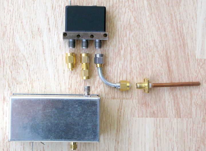 Fig. 5.1 Common Method of Connecting LNA to Feed horn
Figure 5.1 shows a fairly common method of connecting an LNA to a feed horn. The protection of LNA is provided by a miniature relay with SMA type connectors. Inside there are two jumpers, which in turn connect the central port connection to one of the ports at the extreme end. The non-operating jumper is lifted up entirely and pressed against the outside wall of the coaxial line. This provides extremely high yield isolation to the disabled port, which at 1296 MHz can be 80 dB or more. The disadvantage of such a switching mechanism is that the line is broken in two places (the two ends of the jumper). This slightly increases losses and reduces the stability of the contact.
The probe from the receive port of the feed horn is also visible in figure 5.1 and is soldered to an SMA connector. During reception periods the LNA input is connected to the probe. In transmission periods the LNA input is connected to a 50 Ohm load on the relay’s third connector port. It is evident that to signal path it is necessary to have two adapters "male to male” SMA adaptor and at least one angle adaptor.
We now turn to the main issue to losses in the receive signal path. In the second part of this article, it was shown that if the losses are small, the deterioration of the noise factor is numerically equal to these losses. Of course, the reverse is also true, so if we measured the degradation of the noise factor, we know the magnitude of resistive losses. This is the way I conducted my tests because I was able to measure noise factor very well.
Let's look now at the whole chain. Of course the main element of the chain is the relay. Much depends on the relay losses and we can not do anything since these losses since they are what they are after manufacturing. I evaluated several copies of relays from well-known manufacturers and the variation of relay losses was quite large. The best copy showed 0.03 dB (2.1 K), while the worst was 0.067 dB (4.7 K). Unfortunately I had to reject the best copy because from time to time its losses increased sharply. Apparently backlash in the switching mechanism manifested as a lack of reliable switching the two bridges. I deliberately do not mention specific makes of relays and draw only general conclusions from the testing of single copies of relays. According to my measurements a good relay this type of deteriorates receiver noise temperature by about 3 degrees (0.04 dB). I want to clarify that this is only the relay loss from the entrance to the exit (from the female SMA input port to female SMA output port).
We now turn to the rest of the signal path, the two adapters and connectors on the feed horn and the LNA input. The impact of the LNA input connector on the noise factor was discussed in detail in the fourth part of the article and of course this also applies to all other connectors in the system. The measurements show roughly the following picture. One connection with silver plated connectors is 1K. One connection using gold-plated connectors from “known” manufacturers is 2.0- 2.5K. One connection using cheap “no name” gold-plated connectors may exceed 10K. In our case, we have four connections. Even if they give only 2K each, then the amount is 8K plus 3K in the relay for a total of 11K. As a result, the receiver noise temperature of the receive port is more than doubled from just having the LNA with a noise temperature of 9K.
Are there ways to improve on this basic configuration? First, you can easily remove a single connection. Figure 5.2 shows such a modified probe for the feed horn. 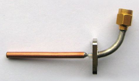 Fig. 5.2 Modified Feed Horn Probe 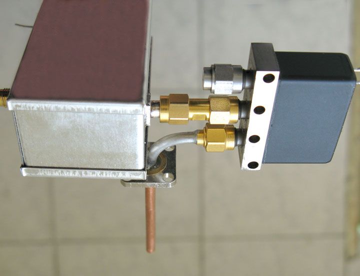 Figure 5.3 Modified Assembly Figure 5.3 shows the modified signal path. These modifications reduce the noise temperature of the system by about two degrees K. You can even go further, if you can use male semi-rigid cable connectors for UT141 cable without using a separate center pin. In this case the role of the connector center pin is performed by the cable center conductor. It has the desired diameter of 0.9 mm and should be only gently blunted, so as not to spoil the connector mating and if the UT141 uses high-quality silvering this eliminates the soldered connection. If you do not have the correct connector you can use a regular one, by just not putting on the pin. The small gap between the center conductor and the PTFE insulation material will have negligible effect on the SWR at this frequency. Figure 5.4 shows the two SMA connector formats, one with regular assembly, and the other without a full-time center pin. 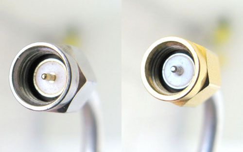 Figure 5.4 SMA connectors – with regular assembly(left), without a full-time center pin(right) Nevertheless, despite all the tricks I could not lower the total losses in the signal path below 6 ... 7K. Let me remind you that in my case the noise temperature of the entire system Ts = 19 K. Then the increment of 6 K is a deterioration of received signal to the noise ratio of 1.2 dB. For EME work this is very noticeable.
After I noticed the instability of losses in my best SMA relay I have tried using a domestic relay type REV-16. With the poor SMA alternatives I had to do something. The isolation of the REV-16 is low at approximately 27 dB at 1296 MHz. However, with the additional isolation within the feed horn, the total insulation provides reliable protection of the LNA input.
First, I created improvised adapters for domestic SMA (CP-50 700th series) connectors. Even in this form the losses were not greater than the best SMA relay and the stability of the switching turned out perfect. This is not surprising since the relay switching ccurs only at one point instead of two that occurs with the regular SMA relays. The poor insulation does add a bit of noise. Let the termination, which is switched to LNA input in transmission mode, has a temperature of 300 K. If the isolation of the relay is 27 dB (x500), then the extra noise is 300K/500 = 0.6K. However it is possible simply not to use termination. An additional benefit of using the REV-16 relay is that in the relay terminals do not stand in one line. Therefore, we can apply direct adapters that are easier to make and have less loss. You can even do without adapters, which I did in the end as I made a probe with the necessary connector as shown in Figure 5.5 and one for the LNA as shown in Figure 5.6. 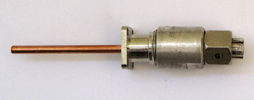 Fig. 5.5 Feed Horn Probe with Integrated Connector 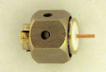 Figure 5.6 Connector for LNA All assemblies mounted on the feed horn are shown in Figure 5.7. The adapter was only for the load. Several other details can be viewed here .
All of these updates will undoubtedly reduce the losses. I think the final result is approximately 5K, and perhaps better. However, the 5K is still a pity to lose. After all, these 5K was so hard to win at the LNA. I started thinking about how to do without a relay. 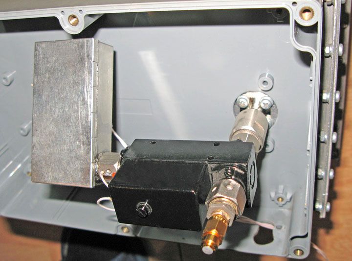 Figure 5.7 All Assemblies Connected to the Feed Horn Option without the relay.At the time when customize the feed horn, I applied a simple way to improve the isolation between transmitting and receiving ports. I placed a small disk in front of the feed horn opening, and then moved it along the axis of the horn to obtain the maximum isolation. Then I changed the diameter of the disk, and again searching for maximum isolation. With two degrees of freedom you can always get the maximum result. This uses a phasing compensation method. Since a small proportion of transmitting power reaches the receiver, if you add to the receiving input the same signal, but with opposite phase, you can achieve a cancellation of the sending signal at the receive port. In my case, part of the transmitter power is reflected from the disk and reaches the receiver input. Selection of the diameter of the disc adjusts the necessary amplitude. The position of the disc on the axis of the horn selects the phase of the reflection. At one fixed frequency the maximum isolation can be obtained however the main problem is stability of the results over time. So, I decided to try this option. I received almost 60 dB isolation after adjustment and even with the full transmitter and no relay, the LNA remained alive. I was afraid of problems at the harmonics of the transmitter, where all this isolation is not working, but nothing happened. It was winter, and I spent about two months in this mode of operation, and I even worked in the EME SSB contest. Problems began when a thaw in the weather occurred with the moisture that has condensed inside the horn. As a result, I lost two good transistors consecutively and stopped the experiment. You can certainly use this variant without relay protection but it is too complicated and unreliable. Antenna switch.Then I started searching some other way to protect the LNA from its own transmitter. I tried several other new options, but I did not like any of them. I tried to lower waveguide protective pins. I tried to add absorbing resistors to these pins. I even tried to lower a plate of RF absorber using the principle of waveguide microwave attenuators. In the end, decided to just pull the probe out of the receiving waveguide at the time of transmission.
It is evident that all these methods were based on mechanical movements. Dima RA3AQ suggested a good idea to use a servo-mechanism from flying model airplanes to provide the motion required to just pull the probe out of the receiving waveguide at the time of transmission with the LNA still attached to the probe. In this case the probe is always connected to the input of LNA. The gap appears only in the outer conductor.
However, we know that in the coaxial line more than 80% of losses are related to the center conductor. In addition the outer conductor is easier to ensure a well-developed contact. My experiments showed that with this version of switching, deterioration of the sensitivity of the receiver is not visible. Comparison with the two options was carried out by measuring the noise ratio of the sun / cold sky. Figure 5.8 shows a stationary probe and the movable probe with a homemade collet on the outer conductor is shown in Figure 5.9. The homemade collet mates with a hole in the wall of the waveguide through the guide sleeve shown in Figure 5.10. 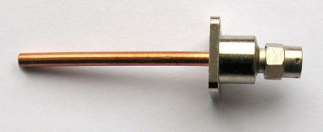 Figure 5.8 A Stationary Probe 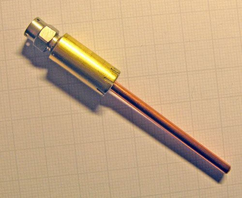 Figure 5.9 Movable Probe with homemade Collet on the Outer Conductor 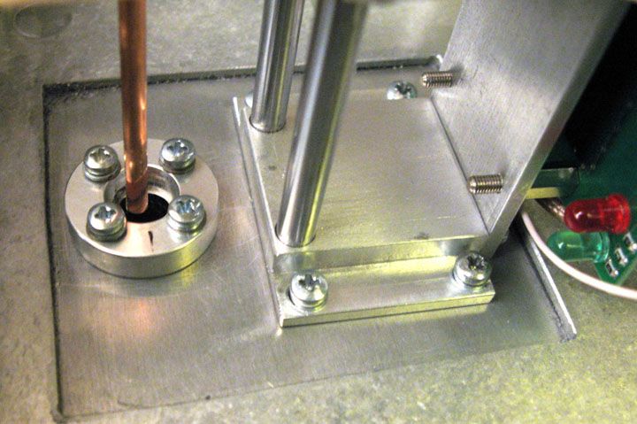 Figure 5.10 Guide Sleeve for Movable Outer Collet 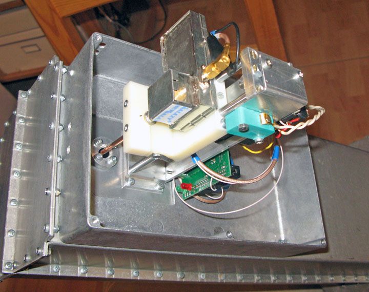 Figure 5.11 The entire device assembly inside a shielded box Figure 5.11 shows the entire device assembly inside a shielded box. One can see two runner racks on which the carriage moves up and down. On the carriage is the fixed probe and LNA. The Wieden limit switch in contact with the carriage in the upper position enables the transmitter. You can also see the controller card that controls movement. 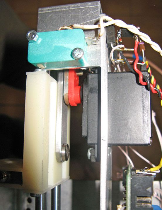 Figure 5.12 HS-475HB Servo Connected to Carriage Figure 5.12 shows the HS-475HB servo crank mechanism that converts the rotary motion into linear movement of the typewriter carriage. Full movement of the carriage corresponds to the rotation of the shaft by180 degrees. The advantage of a crank mechanism is that at the extreme points of motion the rate of carriage displacement falls to zero. Even the rapid movement occurs smoothly and without mechanical shocks. Moreover, the extreme points ensured maximum force. Crank length should be equal to half of the required movement (I have 26mm from the axis to axis).
Connecting rod should be about twice as long (my 58mm). The switching time is determined by the speed of cars and is approximately 1.5 seconds. So that shortened moon echoes are still audible.
I use the following control algorithm. Switching from reception to transmission starts moving the carriage up. In the extreme position the limit switch is triggered which enables the transmitter. After 2 seconds the power to the servo mechanism is removed. The crank mechanism holds the typewriter mechanism at the extreme positions when de-energized. When you switch to the receive operation the servo mechanism is again energized and a little boost voltage (up to 7 V) is used to reduce the switching time. A little later, I had to add one more refinement. At first if in the middle of a movement, the control signal at the switch was removed, and then the mechanism immediately began to slide back. This action broke plastic gears and especially likely to occur when the boosted supply voltage was applied. Now if you remove the control signal before the motion is completed, then the carriage completes the motion and only then comes back. The revised gearbox system works reliably.
Video of the movements of the carriage can be found here . Conclusions.It is evident that losses in receive path can have a major impact on the sensitivity of the receiving system. Often one bad connector can spoil everything.
Each of the options considered has its advantages and disadvantages. A classic solution with a relay draws on its simplicity and durability to provide reasonable operation. If done carefully, this option will add to the overall system noise temperature about seven degrees K. After that, everything depends on the LNA and the antenna. If the total noise temperature of the receiving system is 70 ... 80K (which is very often), then the deterioration is about 10% or 0.4 dB. In principle, not too much. The number of 1296 EME systems with extreme optimization of this proportion is growing. For my station the classic relay system is already deteriorating receive performance by 35%. Being conscious of this figure, if you look what you can do to compensate for such losses, you could add a few square meters to the antenna! In my case, that would be an increase the diameter of the antenna with 3.4m to 4.0m! It is easier to make a homemade antenna switch!
However, here too, it is not done all that easy. What I did is rather to demonstrate the ideas, not a finished product. I need better protection against dust and moisture. The contact made by the brass collet with aluminum walls of the feed horn is very shortlived.
Consideration also must be given for galvanic action between the materials. In general, there is more work to do! Supplement 05/18/2010Recently, an experiment was conducted which confirmed my suspicions regarding the main source of losses in the SMA adaptors. I tried to accurately measure the degradation of the LNA noise temperature with male to male SMA adapters on the input. I checked the four options. Three options are shown in Figure 5.13. The fourth option is a converted adapter № 2. The transformation is the replacement of the central conductor as shown in Figure 5.14. 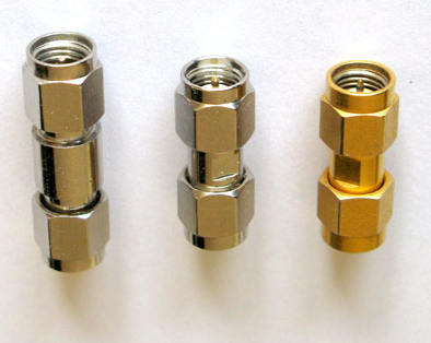 Fig. 5.13 SMA Male to Male Adaptor Options
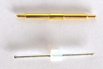 Figure 5.14 Reworked adapter № 2
Inside the adapter two PTFE bushings. In between the gap of about 3mm, is a small segment of the air line. At this point in the housing adapter, the inner diameter is reduced and there is a step for bushings fixation. Accordingly, the central conductor is thickening. When I pulled at one end of the central conductor, it took along with it, one of the PTFE sleeves. The new central conductor made of silver plated semi-rigid cable (0.141 inches) with a piece of teflon cable insulation in the middle. This adjusts the impedance and, at the same time, does not allow the wire to fall out.
So we have four options for the adapter. The first two samples with a cheap goldplated center conductor. The third is a gold plated (high quality) path adapter and the fourth is an altered a cheap adapter.
The results of measurements of the noise figure LNA are shown below and the last column shows the degradation of noise temperature.
# 1 0.261 dB + 9.0K
# 2 0.202 dB +4.9 K
# 3 0.171 dB +2.7 K
# 4 0.140 dB +0.6 K
We see that the issue of cheap adapter is only with the central conductor, at least for the range of 1296 MHz. It seems that it is made from lightly gilded nickel. Still the results of the expensive adapter do not shine. Unfortunately, this substitution is possible only for "male to male" SMA. Some consolation is that our (Russian) silver "female" SMA connector is universal. It is suitable for both metric and inch thread for import.
|